

Learn the basics of optical dielectric multi-layer filters
How does an interference filter work?
Interference filters are very effective to accomplish almost any type of spectral optical filtering. Typical examples are short-wave pass, long-wave pass and bandpass filters. But also, more complex filters like multi-bandpass filters, continuously variable filters and dichroics can be implemented.
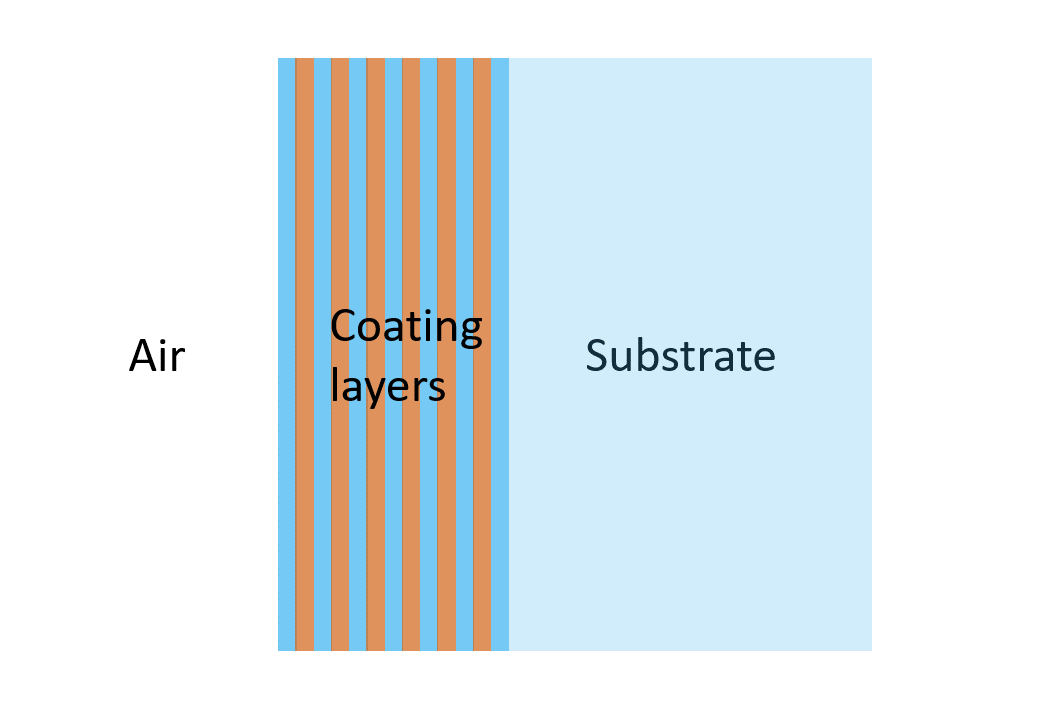
One of the key benefits of interference filters is, that almost any spectral filtering function can be designed and implemented. An interference filter consists of a flat substrate (often glass) with many thin coated layers of dielectric materials on either one side or both sides of the substrate. The coating layers alternate between a material with high and low index of refraction.
This technical note explains the fundamentals behind how an interference filter works.
Interface between two dielectric layers
Before investigating how the dielectric layers form an interference filter, it is useful to look at the interface between two layers.
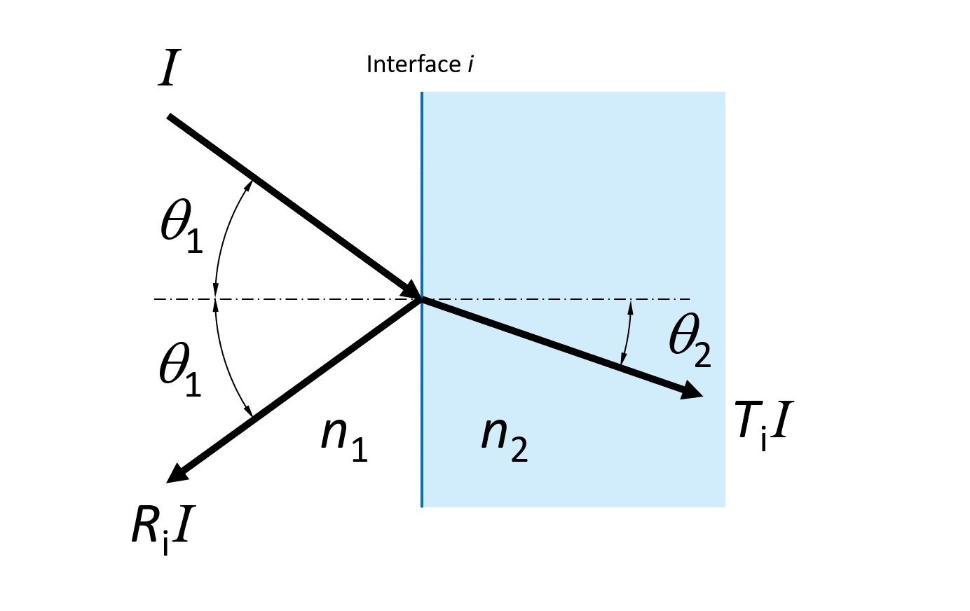
When light is incident on the interface (labeled i), some fraction (Ri) of the light intensity is reflected and some fraction (Ti) is transmitted. If we assume that the interface is loss-less, which is a good approximation for dielectrics, the conservation of energy dictates that:
Ti = 1 – Ri
The relation between the angle of the incidence and the transmitted light relative to the normal is given by Snell’s law of refraction:
n1 sin(θ1) = n2 sin(θ2)
The reflection and transmission (intensity) coefficients are different for the s- and p-polarized light and depend on the refractive indices and angle of incidence as follows:
| Rs = ( |
|
)2 |
Ts = 1 – Rs
| Rs = ( |
|
)2 |
Tp = 1 – Rp
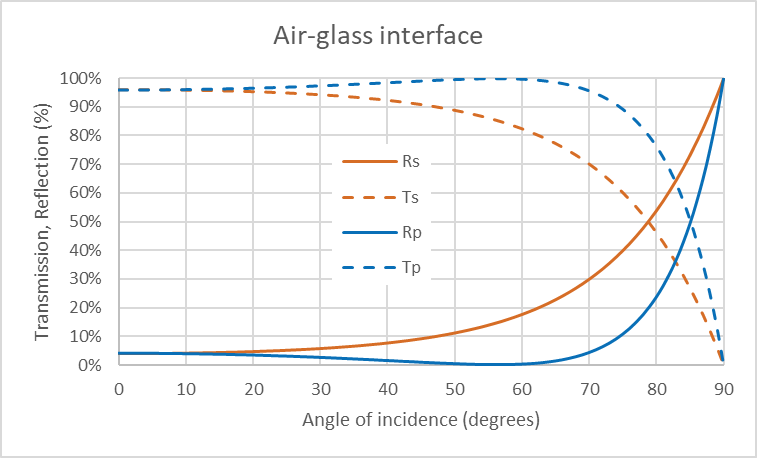
For the interface between air (n1 = 1) and glass (n2 = 1.5) the reflection and transmission coefficients for the s- and p-polarized light as a function of angle of incidence are shown on Figure 3.
Single dielectric layer
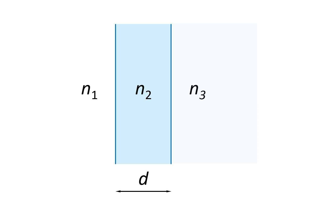
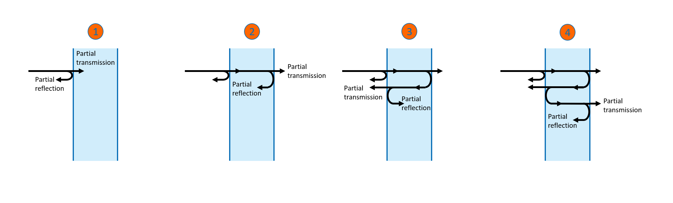
Often, interference filters employ hundreds of coating layers but, to understand the fundamentals, we will consider only a single dielectric layer as shown on Figure 4. The dielectric layer has a thickness d and a refractive index n2 and is surrounded by a media of refractive index n1 to the left and n3 to the right.
When light is incident on the surface of the dielectric layer from left, some fraction of the light is transmitted through the surface and the remaining light is reflected as indicated on drawing 1 on Figure 5. Drawings 2 to 4 illustrate how the light transmitted into the dielectric layer bounces back and forth between the two surfaces and, for every bounce, some amount of light is transmitted through the surface. Figure 5 only shows the first few bounces but there is an infinite number of reflections and transmissions taking place.
On each side of the dielectric layer, we end up with a sum of transmitted (forward moving) waves and a sum of reflected (backwards moving) waves. If the forward moving waves are all in phase, as shown on Figure 6, the waves add up to produce maximum transmitted light through the dielectric layer. Consequently, the backwards moving waves will be out of phase and minimal amount of light is reflected.
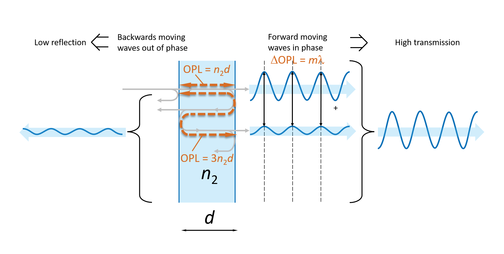
For the forward moving waves to be all in phase the difference between the Optical Path Length (OPL) each wave experiences when traveling through the dielectric layer should be an integer number m of wavelengths λ. This can be written as:
ΔOPL = mλ
The optical path length equals the distance travelled in a medium multiplied with the refractive index of the medium. This means that the OPLs for the directly transmitted and the first double reflected wave through the dielectric layer (see Figure 6) are
OPL(directly transmitted) = n2d
OPL(double reflected) = 3n2d
and thereby
ΔOPL = 2n2d
In the case where we want maximum transmission through the dielectric layer, ΔOPL should equal an integer number of wavelengths (ΔOPL = mλ) which means that for maximum transmission the thickness of the layer should satisfy the following condition
d = mλ / 2n2
From this analysis we can also conclude that for a given thickness and refractive index of a dielectric layer, there will be maximum transmission at the following wavelengths:
λpeak = 2n2d / m
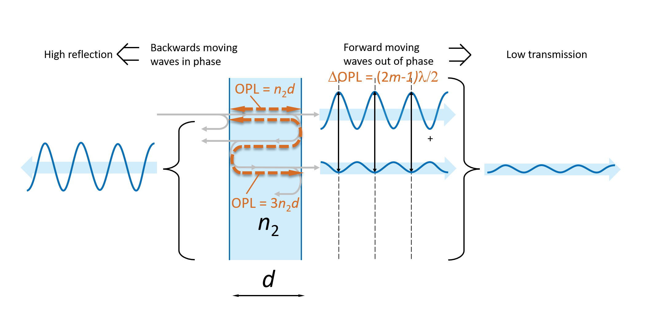
In the case, where the forward moving waves add up out of phase the optical path length differences equal an uneven number of half-wavelengths:
ΔOPL = (2m-1)λ / 2
as illustrated on Figure 7.
The actual maximum and minimum transmitted light depends on the reflection coefficient Ri at each of the two surfaces i = I and II, respectively. For the case where n1 = n3, the two reflection coefficients become identical, hence RI = RII = R. In this simplified case, it can be shown that the total transmission Ttot is given by the following equation
| Ttot = |
|
Where the plus-sign in the denominator is used when n2 < n1 and the minus sign when n2 > n1.

Download this White Paper
Download this White Paper
Take advantage of this opportunity to expand your knowledge and accelerate your research.
Download this current white paper
Multi-layer coatings
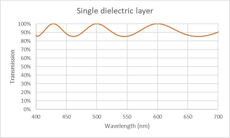
As just described a single dielectric coating layer will produce an optical filter with maximum transmission at the wavelengths given by λpeak = 2n2d / m, , where m is an integer. The spectral transmission of such a filter is shown on Figure 8 for the case where d = 1 micrometer and n2 = 1.5 and the reflection R at each surface is 4 %. Although the filter does provide maximum and minimum transmissions as expected it is not a very useful filter.
A common type of filter function is Anti-Reflection (AR) coatings, which reduce the reflection at an air-glass interface and thereby improves the transmission. A simple AR-coating can be made with a single layer of MgF2, which has a refractive index around 1.38, and a thickness of λ/4. Such a MgF2 layer can reduce the reflection from 4% to around 1%.
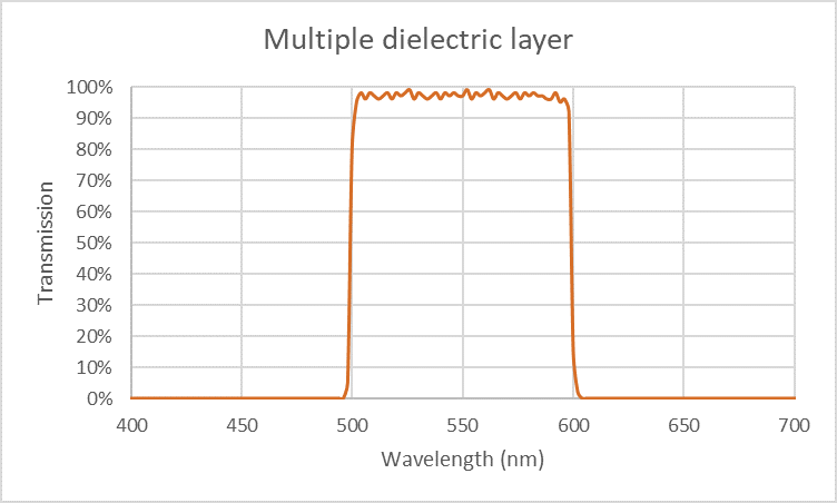
To design more advanced filters, it is necessary to add many dielectric layers of alternating high and low refractive index. In this way it is possible to make a bandpass filter like shown on Figure 9 with a nice high transmission in the pass-band and strong rejection outside the passband.
Other common types of optical filter function are long wave pass and short wave pass edge filters, notch filters, and intensity, wavelength or polarization beam splitters. Also, even more advanced filters can be manufacutred by combining several filter functions in the same coating. One example is multi-bandpass filters which provides several wavelengths pass bands in the same filter.
Learn more
Delta Optical Thin Film has more than 50 years of experience in design and manufacture of advanced interference filters. We have pioneered many innovative solutions that are now commonly used in analytical instruments.
Browse through the many examples of products we have made on our product pages.
Meet the author
Stay updated on our expert insights
Get the latest news and insights about optical filters – subscribe to our newsletter.