



Learn how Continuously Variable Bandpass Filters solve a common challenge in laser scanning systems.
Custom Variable Bandpass Filters improve contrast in laser imaging inspection
Introduction
Laser line-scan imaging has become a widely adopted technique for the inspection of large infrastructure assets, industrial materials, and manufactured components. In applications such as railway track and pantograph inspection, a laser line is projected onto the target surface and captured by a high-resolution line-scan camera, enabling continuous imaging at high speed and over large areas. To maximize image quality and measurement accuracy, these systems commonly employ narrow bandpass filters that transmit the laser wavelength while suppressing ambient light.
While this approach is highly effective, the performance of conventional interference bandpass filters is fundamentally influenced by the angle of incidence of incoming light. As imaging systems are designed with increasingly wide fields of view, light rays reach the filter at a range of angles, causing the filter’s center wavelength to shift across the image. The challenge is especially pronounced in outdoor inspection systems such as railway track monitoring, where changing sunlight conditions and wide scan widths place stringent demands on image contrast and signal consistency.
Traditional approaches, including increasing the working distance or selecting a broader filter bandwidth, can partially mitigate the problem but often introduce new compromises related to system size, optical efficiency, or ambient light suppression.
This paper presents a custom optical filtering solution developed by Delta Optical Thin Film to address this challenge. By combining a continuously varying spectral response with a tailored understanding of the imaging geometry, a Continuously Variable Bandpass Filter can compensate for the angle-induced wavelength shift that limits conventional filters. The result is a filter that maintains the desired spectral performance across the entire field of view, enabling improved image contrast, more effective suppression of ambient light, and enhanced system performance in demanding laser line-scan applications.
Laser line-scan inspection of railway tracks and pantographs
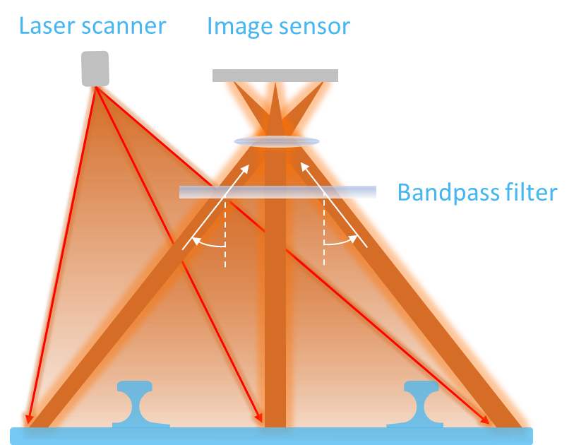
Laser line-scan imaging is widely used for the automated inspection of railway tracks and pantographs, where large sections of rail infrastructure must be monitored at high speed and with high accuracy. In a typical system, a laser projects a narrow line across the width of the rail or pantograph and surrounding track structure. A line-scan camera captures successive image lines as the inspection vehicle moves along the track, creating a continuous high-resolution image of the inspected surfaces.
To achieve robust operation under varying outdoor lighting conditions, a narrow bandpass filter is typically placed in front of the camera sensor. The filter is designed to transmit the laser wavelength while rejecting sunlight and other sources of ambient illumination, thereby maximizing image contrast and signal-to-noise ratio.

The challenge of conventional interference filters
To maximize image contrast, laser line-scan systems typically employ narrow bandpass interference filters centered at the laser wavelength. These filters efficiently transmit the laser signal while rejecting sunlight and other sources of background illumination.
However, interference filters exhibit an inherent dependency on the angle of incidence of incoming light. As light enters the filter at increasing angles, the center wavelength shifts toward shorter wavelengths. In wide-field imaging systems, rays originating from different parts of the scene therefore experience different filter characteristics.
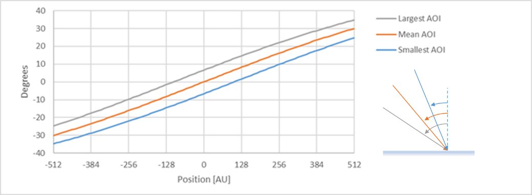
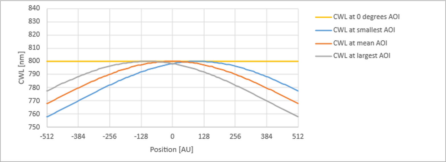
The upper graph in Figure 2 shows a realistic example of the variation in angle of incidence (AOI) across a bandpass filter, together with the angular spread around the nominal AOI (the minimum and maximum AOI at each position). The lower graph shows the resulting shift in the effective center wavelength of the bandpass filter as a function of position. As can be seen, the center wavelength changes by approximately 30 nm, which is a relatively large shift for a narrowband laser line filter.
For railway inspection systems, which often require a wide field of view to cover the complete rail profile and surrounding structures, this effect can become significant. Rays near the center of the image pass through the filter at small angles and experience the intended spectral response, while rays near the edges encounter larger angles and a shifted filter response. Consequently, transmission of the laser wavelength may decrease towards the image edges, while suppression of ambient light becomes less effective.
The result is non-uniform image quality across the field of view, potentially reducing measurement accuracy and lowering the signal-to-background ratio in outdoor environments.
Traditional solutions to angle-dependent band-pass
Traditionally, system designers have relied on two main approaches to reduce the impact of angle-dependent wavelength shift of conventional interference filters.
The first approach is to increase the working distance between the camera and the object being inspected. By moving the camera farther away, the range of angles entering the optical system is reduced, which in turn minimizes the wavelength shift experienced by the bandpass filter. However, while increasing the working distance reduces the variation in angle of incidence across the field of view, it does not eliminate it entirely. As a result, residual wavelength shifts and variations in filter performance remain present, particularly in systems with wide fields of view. Also, this solution results in a larger and less practical system, which may not be desirable in space-constrained inspection platforms.
The second approach is to use a bandpass filter with a wider spectral bandwidth. A broader passband makes the system less sensitive to angle-induced wavelength shifts because the laser wavelength remains within the transmission band across a larger range of incidence angles. However, the wider bandwidth also allows more ambient light to reach the sensor, reducing image contrast and lowering the signal-to-background ratio, particularly in outdoor environments.
Both approaches can help mitigate the effects of angle-dependent wavelength shifts, but neither addresses the root cause of the problem. Instead, they introduce compromises between system size, ambient light rejection, and imaging performance.
Continously Variable Bandpass Filter solution
To overcome the limitations of traditional approaches, Delta Optical Thin Film has developed a Continuously Variable Bandpass Filter (CVBPF) specifically designed to compensate for the angle-dependent wavelength shift inherent to wide-field imaging systems.
Unlike a conventional bandpass filter, which has the same center wavelength across its entire surface, a CVBPF is intentionally designed with a center wavelength that varies continuously along one dimension of the filter. This gradual spectral variation can be precisely tailored during the optical coating design and manufacturing process to match the geometry of a specific imaging system.
Designing the compensation
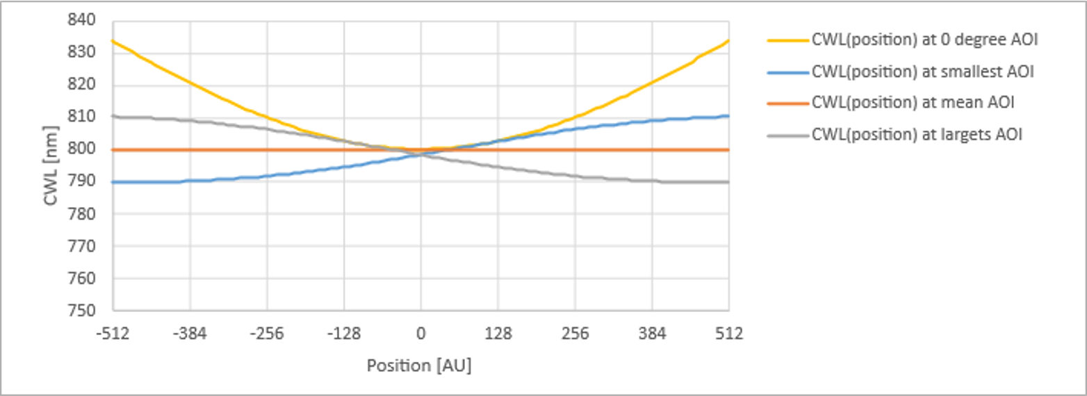
The key to the solution is understanding how the center wavelength of a conventional interference filter changes across the field of view. For a given camera, lens, and working distance, it is possible to calculate the average angle of incidence experienced by rays originating from different positions within the image. This allows the corresponding wavelength shift to be mapped across the entire field of view.
The CVBPF is then designed with an opposing wavelength variation, as depicted by the orange curve in Figure 3. The filter’s center wavelength increases continuously toward the edges of the filter. When combined with the angle-induced wavelength shift, these two effects largely cancel each other out, as illustrated by the red curve.
The compensation can be implemented with the filter positioned either in front of the imaging lens or within the optical system, depending on the application requirements and available space.
It should be noted, that due to the finite aperture of the imaging lens, a bundle of rays reaches the filter, resulting in a distribution of incidence angles around the nominal field angle. While a Continuously Variable Bandpass Filter can compensate for the field-dependent shift of the mean angle of incidence, it cannot compensate for the wavelength broadening associated with this angular distribution. Consequently, the residual spectral broadening remains determined by the lens F-number and the optical design of the imaging system.
Summary
Laser line-scan imaging systems rely on narrow bandpass filters to maximize image contrast and suppress unwanted ambient light. However, as fields of view become wider, the angle-dependent behavior of conventional interference filters can lead to significant variations in spectral performance across the image. In applications such as railway track and pantograph inspection, this effect may result in reduced laser transmission, increased sensitivity to ambient light, and non-uniform image quality.
Traditional mitigation strategies, such as increasing the working distance or widening the filter bandwidth, can reduce the impact of angle-induced wavelength shifts, but they often introduce compromises in system size, optical performance, or ambient light rejection. Furthermore, they do not address the underlying cause of the problem.
Continuously Variable Bandpass Filters offer a different approach. By introducing a controlled variation in center wavelength across the filter surface, the filter can be tailored to compensate for the field-dependent angle-of-incidence shift of a specific optical system. This enables a uniform spectral response across the entire field of view, maintaining high transmission of the laser wavelength while preserving effective suppression of ambient light. The result is a more uniform and robust imaging system without the need for larger system geometries or broader filter bandwidths.
This example demonstrates how advanced optical filter design can be used not only to meet a spectral specification, but also to solve application-specific system challenges. By tailoring the filter characteristics to the imaging geometry, Continuously Variable Bandpass Filters enable new levels of performance in demanding laser imaging applications, including railway inspection, industrial machine vision, and other wide-field laser sensing systems.
Meet the author

Stay updated on our expert insights
Get the latest news and insights about optical filters – subscribe to our newsletter.