

Key Spectrometer Parameters Needed for Optimal CVOSF Selection
How to request an order sorting filter
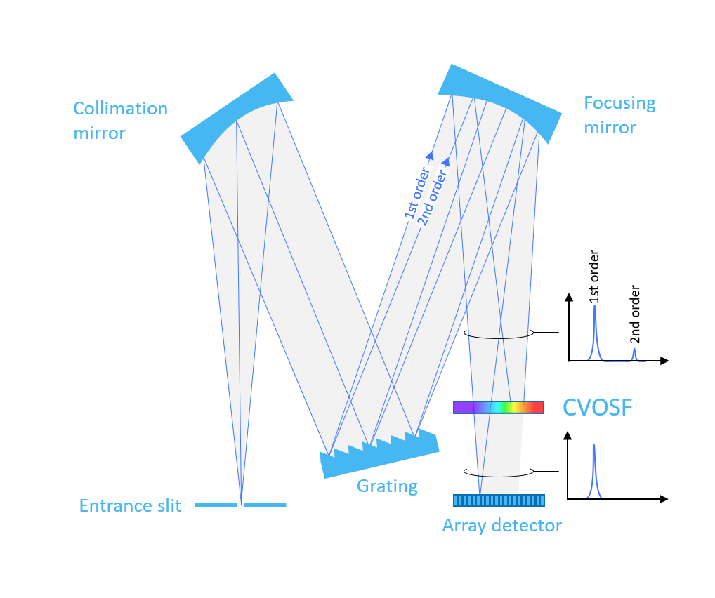
The multiple orders from diffraction gratings become problematic in diode array spectrometers when the detected spectrum covers more than one octave. In this situation, the orders overlap and it is therefore difficult to interpret the detected spectrum. The solution is to insert an order sorting filter in the spectrometer immediately before the detector. This technical note describes how to specify a Continuously Variable Order Sorting Filter (CVOSF).

Definitions
In order to identify the best CVOSF for your spectrometer, it is important for Delta Optical Thin Film to know a few key parameters of your spectrometer design. Figure 1 shows schematically how the wavelength depends on beam position on the filter for the 1st, 2nd and 3rd order.
It is important to note that the range of wavelengths that potentially could reach and be detected by the detector can be larger than the wavelength range, the spectrometer is designed for. For instance, some detectors might be sensitive down to 180 nm. Even if the spectrometer is designed to detect for example λ1st, start = 250 nm to λ1st, end = 1050 nm of 1st order light, 2nd and 3rd order ambient light between 180 to 250 nm might also be detected.
The lowest detectable wavelength λho,start can be limited by several factors like the UV-absorption in a cover glass on the detector or an optical bandpass filter at the entrance to the spectrometer.
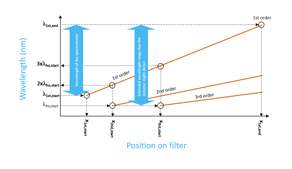
The following four 1st order wavelengths defined on Figure 1 and their positions on the filter are key:
- λ1st, start The shortest wavelength of 1st order light, that the spectrometer is designed for
- 2xλho,start 2x the shortest wavelength of higher order light that the detector might detect
- 3xλho, start 3x the shortest wavelength of higher order light that the detector might detect
- λ1st,end The longest wavelength of 1st order light, that the spectrometer is designed for
Order locations, AOI-range and beam spots


In order to choose the best CVOSF design for your spectrometer we kindly ask you to supply the following information (see Figure 1, Figure 2 and Figure 3 for definitions):
- The shortest and longest 1st order wavelength that is incident on the detector in your spectrometer
- The shortest higher-order wavelength to reject
- The positions along the x-axis on the filter of the chief ray of the following four 1st order wavelengths λ1st, start, 2xλho,start, 3xλho, start and λ1st,end
- The minimum and maximum Angle of Incidence (AOI) of λ1st, start, 2xλho,start, 3xλho, start and λ1st,end. Please, provide the AOIs signed such that angles on opposite sides of the normal have opposite signs.
- The beam spot width on the filter of λ1st, start, 2xλho,start, 3xλho, start and λ1st,end.
The Figure below shows an example of a filter specification for a 300 – 1100 nm spectrometer. You can download the Excel sheet here, enter your own specifications and send it to us to initiate the discussion.

Download this White Paper
Take advantage of this opportunity to expand your knowledge and accelerate your research.
Download this current white paper
Dimensions and substrate material

With reference to Figure 5 please, specify the following parameters for the filter. Typically, tolerances are +/- 0.1 mm except for D which typically has a tolerance of +/- 0.5 mm. The standard substrate material is UV-grade fused silica. Please contact us if you require a non-standard substrate material.

Our filters are inspected for visual defects according to ISO 10110-7 and we generally fulfill the following specification: 5×0.1;Lx0.06;E0.25 (5 grade 0.1 defects; long scratches maximum 0.06 mm width; Edge chips maximum 0.25mm from edge).
Meet the author
Stay updated on our expert insights
Get the latest news and insights about optical filters – subscribe to our newsletter.